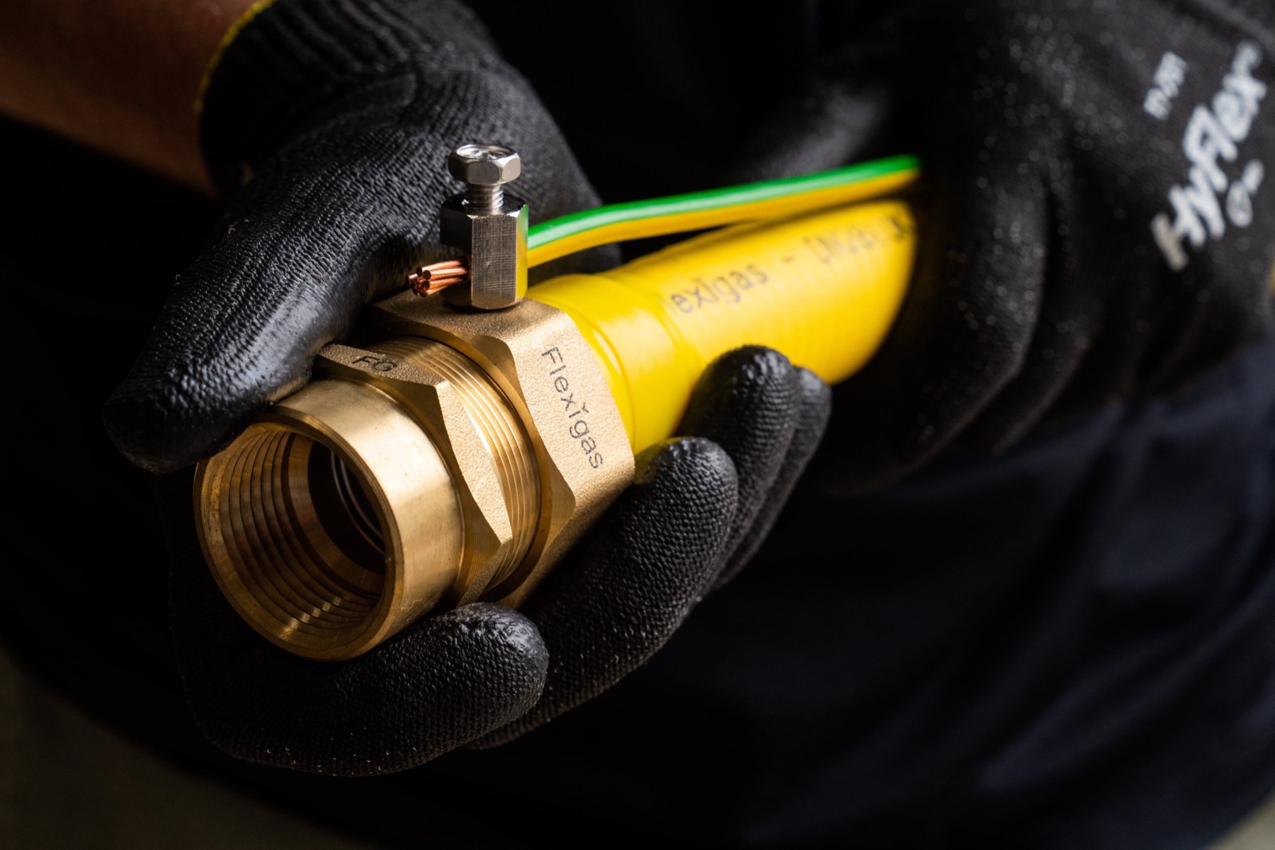
Metallic gas pipework has to be main bonded. BS 7671 calls for main protective (equipotential) bonding of the gas installation, and BS 6891 requires it on every Flexigas install, exactly as it does on copper. Land the main bond as near as practicable to the point the gas enters the building, within 600mm of the meter outlet union, before any branch in the pipework, on accessible pipework you can see. Use a 10mm² green-and-yellow conductor (6491X to BS 6004). The bonding clamp is to BS 951:2009. What FG Bond changes is the hardware: the earthing terminal is built into the Flexigas fitting (an integrated bonding nut), so you land the bond at the fitting with the supplied "Safety electrical connection, do not remove" label fitted between the terminal and the nut. No separate clamp to source and fit, and it is less fiddly. Strip 1cm to 2cm of the earth conductor and run it parallel to the tube. Same regulation, same result, faster on site.
A practical reference on main protective bonding for Gas Safe registered engineers fitting Flexigas Corrugated Stainless Steel Tubing. It covers why metallic gas pipework must be bonded, where the main bond connects, the conductor and clamp specification, and how the integrated FG Bond terminal makes the job quicker. No marketing copy. Just what you need to get the bond right and signed off.
1. Why metallic gas pipework must be bonded
Main protective bonding (also called main equipotential bonding) ties the metallic services in a building to the main earthing terminal so that exposed and extraneous metalwork sits at the same potential. If a fault puts a voltage on one metal part, bonding holds everything else at the same level, so there is no dangerous potential difference for a person to bridge.
Metallic gas pipework is an extraneous-conductive-part. Flexigas is corrugated 316L stainless steel with brass fittings, so it conducts, and that means it falls inside the same bonding requirement as copper or steel gas pipe. The relevant rule is BS 7671 (the IET Wiring Regulations) for the electrical side, and BS 6891 for the gas installation. Both require the gas installation to be main bonded.
The Flexigas Installation Manual states it plainly: all domestic gas installations, including CSST systems such as Flexigas, shall have main equipotential bonding of the gas installation pipework conforming to BS 7671. This is not optional, and it is not something the integrated FG Bond terminal removes. FG Bond makes the connection easier, not unnecessary.
2. Where the main bond connects
The position of the main bond matters as much as the connection itself. Get it in the wrong place and it fails on inspection even if the clamp is sound. The main equipotential bonding conductor shall be connected:
- As near as practicable to the point of entry into the premises, where the gas enters the building.
- Before any branch in the installation pipework, so the whole installation is bonded by the single main connection.
- Within 600mm of the meter outlet union for an internal meter, so the connection can be verified at inspection.
- In an accessible position where it can be visually observed, fitted with the "Safety electrical connection, do not remove" warning label.
- By a connection that is mechanically and electrically sound and not subject to corrosion.
To put the 600mm rule in context: the bond goes on the installation pipework downstream of the meter, close to the meter outlet union, not on the service side and not on the flexible meter connector. It is the first place you reach the rigid, bondable part of the installation as it leaves the meter and before it splits to feed appliances.
3. The conductor and the clamp
Bonding conductor sizing
For a typical domestic gas installation the main bonding conductor specification per BS 7671 is:
- Minimum cross-sectional area 10mm²
- Green and yellow insulation
- Construction reference 6491X, conforming to BS 6004
10mm² is the standard main protective bonding size for most domestic supplies. Larger supplies can call for a bigger conductor sized against the supply neutral, so check the specifics of the installation against BS 7671 where the supply is anything other than a standard single-phase domestic service. When in doubt, the electrical designer or the distributor's earthing arrangement governs the size.
The bonding clamp
Where a separate clamp is used, it must be a bonding clamp to BS 951:2009, the British Standard for earthing and bonding clamps. The clamp must carry the "Safety electrical connection, do not remove" label.
One important constraint on Flexigas: a separate clamp cannot be attached to the stainless steel tubing directly, nor to any flexible connector near the meter. A separate BS 951 clamp may only be attached to the hex part of the Flexigas fittings, or to the copper or rigid steel parts of the gas installation. The corrugated tube is not a clamping surface.
4. How FG Bond changes it
Here is the practical difference on site. With FG Bond, the earthing terminal is built into the Flexigas fitting as an integrated bonding nut. It has been tested by BSI to meet BS 951:2009 for use as a bonding clamp, so it satisfies BS 6891 and BS 7671 for equipotential bonding of the gas pipework in its own right.
That means you do not source, carry and fit a separate clamp. You land the bond directly at the fitting. The job is the same regulation and the same outcome, with less hardware and less fiddling around the meter.
Landing the bond on an FG Bond fitting
- Fit the bonding nut to the fitting body using the pre-drilled holes.
- Fit the warning label. Place the "Safety electrical connection, do not remove" label between the earthing terminal and the Flexigas nut. The plastic label has a small hole that the earthing terminal passes through, so it sits captive between the terminal and the nut.
- Strip the conductor. Strip back the green-and-yellow earth conductor to reveal 1cm to 2cm of copper wire, no more, so there is no bare conductor left exposed outside the terminal.
- Land it parallel to the tube. Feed the stripped copper into the FG Bond terminal and screw down onto the copper wire with the cable running parallel to the tubing. Running the conductor along the tube keeps it tidy and supported rather than standing proud where it can be knocked.
- Connect back to the main earthing terminal at the other end, completing the main bond.
That is the whole connection. The integrated terminal carries the BS 951 approval, the label is built into the assembly, and the conductor lands without a separate clamp.
5. A separate BS 951 clamp is still acceptable
FG Bond is the faster route, but it is not the only compliant one. A separate BS 951:2009 bonding clamp remains perfectly acceptable on a Flexigas installation. The points to remember are the placement rule and the surface rule: the clamp goes in the right position (Section 2), and it goes on the hex part of a fitting or on the copper or rigid steel parts of the installation, never on the stainless tube or a flexible connector (Section 3).
So you have two routes to the same compliant main bond: the integrated FG Bond terminal, or a separate BS 951 clamp on a bondable surface. Pick whichever suits the installation. On a Flexigas job the integrated terminal is usually quicker because the bondable surface and the terminal are the same fitting.
6. When you find an unbonded gas installation
If you connect installation pipework to a primary meter and find the system is not bonded, the Manual is specific. Regulation 18(2) of the Gas Safety (Installation and Use) Regulations 1998 requires you to inform the responsible person for the premises that bonding should be carried out by a competent person.
The Installation Manual provides a notification card template you can copy, headed "Main protective bonding conductor". Use it. Recording the advice protects you and gets the omission put right by whoever is competent to do the electrical work.
7. Temporary continuity bonds
Main protective bonding is the permanent connection. Separately, during any work that requires connection or disconnection of metal installation pipework, fit a temporary continuity bond where producing a spark or a shock could cause a hazard, whether or not permanent equipotential bonding is already established. The temporary bond keeps both sides of a break at the same potential while you work.
The recommended temporary bond is at least 1.2m of single-core insulated flexible cable, or equivalent, of at least 250V rating, cross-sectional area not less than 10mm², multi-strand flexible construction generally in accordance with BS 6004, BS 6007 or BS 6231, with a robust clip or clamp firmly attached at each end. Leave the bond in position until the work is completed and metallic continuity is re-established.
8. Common mistakes
- Clamping the stainless tube. A separate clamp must never go on the corrugated stainless steel or on a flexible connector. Use the hex of a fitting, the copper or rigid steel, or the FG Bond integrated terminal.
- Bonding after a branch. The main bond goes before any branch in the installation pipework, so the whole installation is covered.
- Too far from the meter. For an internal meter, the connection should be within 600mm of the meter outlet for verification.
- No warning label. The "Safety electrical connection, do not remove" label has to be fitted at the connection. On FG Bond it sits between the terminal and the nut.
- Leaving bare conductor. Strip only 1cm to 2cm so there is no exposed copper outside the terminal, and run the conductor parallel to the tube.
- Undersized conductor. 10mm² green-and-yellow 6491X is the standard domestic main bonding size; check BS 7671 for larger supplies.
- Walking away from an unbonded system. Regulation 18(2) requires you to notify the responsible person in writing. Use the Manual's notification card.